Micrometer What is it?
 |
| Micrometer Calibration |
A micrometer, sometimes known as the size of the screw micrometer, is a device combining a calibrated screw is widely used for precise measurement of small distances in mechanical engineering and machinery as well as most mechanical trading, along with other metrological instruments such as dial, vernier and digital calipers . Micrometer often, but not always, in the form of calipers.
How to Operate a Micrometer?
Using a micrometer screw principle to strengthen the small distances that are too small to measure directly the rotation of the screw is large enough to be read from the scale. The accuracy comes from the accuracy micrometer threadform that at its core. Basic operating principles of a micrometer is as follows:
The amount of rotation of a screw can be accurately made directly and precisely correlated with a certain amount of axial movement (and vice versa), through a constant known as the lead screw that. A lead screw is moving forward with the axial distance of one complete revolution (360 °). (In most of the yarn [ie, all threads in a single-start], lead and pitch refers to basically the same concept.)
With the right lead and a major diameter screw, a given amount of axial movement will be strengthened in a circular motion generated.
For example, if the lead screw is 1 mm, but large diameter (here, outer diameter) is 10 mm, the circumference of 10π screw, or about 31.4 mm. Therefore, axial movement of 1 mm reinforced (enlarged) for movement around 31.4 mm. This allows amplification of small differences in the size of two objects that are measured together to correlate the large difference in the position of the micrometer thimble.
In older micrometer thimble position is read directly from the scale marks on the thimble and the spindle. A Vernier scale is usually included, which allows the position to be read for a fraction of the smallest scale marks. In the newer digital micrometer, electronic readout that displays digital length on the LCD screen on the instrument. There are also mechanical digit version, such as car odometers style in which the number "roll over".
Different Types of Micrometer
Basic Types of Micrometer
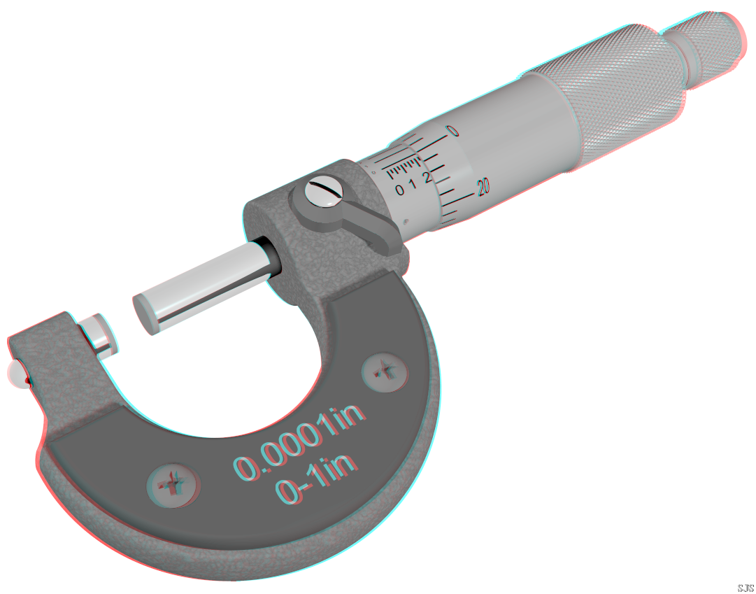
Top image shows the three most common types of micrometers, the names based on their application:
Outside micrometer (aka micrometer calipers), typically used to measure wires, spheres, shafts and blocks.
Inside micrometer, was used to measure the diameter of the hole.
Depth micrometer, measure the depth of slots and steps.
Special Type Micormeter
Each type of micrometer caliper can be fitted with a special ground spindle and tips for specific measurement tasks. For example, the foundation can be established in the form of screw thread segments, in the form of v-blocks, or in the form of large discs.
Universal micrometer sets come with interchangeable base, such as spline flat, round, disk, blades, points, and knife-edge. Universal micrometer long can also refer to a type of micrometer is frame has modular components, allowing one to function as a mic outside micrometers, depth mic, step mic, etc. (often known by the brand name Mul-T-Anvil and the Uni-mike).
Micrometers have a set of knives that fit a narrow tips (blades). They allow, for example, measurement of o-ring groove narrow.
Pitch-micrometer diameter (aka thread mic) having a set of matching thread-shaped tips for measuring the pitch diameter of screw threads.
Limit your mic has two base and two spindles, and is used as a flash meter. The part being inspected must pass through the first gap and must stop at the second gap to be within specification. Two gaps accurately reflect the top and bottom of the tolerance range.
Bore micrometer, usually the head of the runway at the base of three micrometers are used to accurately measure the inside diameter.
Micrometer tube has a cylindrical base positioned perpendicular to the spindle and used to measure the thickness of the tube.
Micrometer stop essentially the mic mounted on a manual milling machine table, bedways of a lathe or other machine tool, in place of simple stops. They assist the operator to precisely position the table or train. Quitting can also be used to run the kickout mechanism or limit switches to stop the automatic feed system.
Micrometer ball has a spherical (ball) runway. They may have one flat and one ground ball, in which case they are used to measure the thickness of the tube wall, the distance from the hole to the edge, and the other a distance where the foundation should be placed against the rounded surfaces. They differ in the application of the micrometer tubes in that they can be used to measure against the rounded surfaces that are not tubes, but grounding the ball may also not be able to get into a small tube is as easy as micrometer tubes. Micrometer balls with a pair of balls can be used when the tangential-contact point desired on both sides. The most common example is in measuring the pitch diameter of screw threads (which is also done with a conical base or 3-wire method, the latter of which uses the same geometry as an approach to couple-of-ball).
How to Calibrate a Micrometer?
1. Zero error
Micrometer zero error checked and if zero errors are observed which can be set equal to zero by adjusting the barrel of the maxim, if possible, zero error should be indicated in the results of calibration and compensation in the final report.
Errors in the scale is determined by measuring the slip of the following measures:
2.5, 5.1, 7.7, 10.3, 12.9, 15.0, 20.0, 17.6, 20.2, 22.8 and 25 mm (IS 2967:1983)
2. Boredom
Flatness error is checked by keeping the optical flat on the ground each under monochromatic light. A number of disorders colored edges will be visible on their surfaces. Flat adjusted such that the minimum number of bands obtained. To tolerances specified in faltness, maximum four bands have formed. Flatness is defined as an nxl / 2, where n is the number of bands and l is the wavelength of light used.
3. Parallelism
Parallelism between the two base error was tested by optical parallel gripping three different thicknesses of different positions which include a circular scale.
In each case the number of edges appearing on the second runway are calculated together. Of the three cases, the assessment of parallelism on the basis of the maximum number of edges.
Flat is placed between the faces measured and adjusted in a way so that the number of bands seen on one face of interference are minimal. The number of bands on the other face is calculated which generally should not exceed 8, to 0-25 mm. Recommended thickness of the optical flat is 12.5, 12.625, 12.750 and 12.875 mm.
Parallelism error between the runway = N x λ / 2
Where 'N' is the maximum number of edges appearing on the second runway and λ is the wavelength of light used.
4. This micrometer micrometer clamp mounted in the stands.
5. Temperature before starting the calibration is recorded on data sheets.
6. Slip gauges measured one by one in order to improve and then in the corresponding readings of the micrometer (estimated to be 1/5th scale circular division recorded on data sheets the same procedure followed in decreasing order and the micrometer readings. Recorded on data sheets. This form of Two sets of such sets of measurements of the measurement is taken to make a total of four observations at each measuring slip ..
7. Temperature after the measurement is recorded.
See also: